With this option enabled, on save the length and width of the flat pattern of the Sheet Metal part are stored in two separate Custom iProperties.
Specifies the number of decimals shown for the length and width.
Trailing zeros are shown behind the comma.
Enter the unit in which the length and width are noted.
By enabling this option, the unit will be displayed behind the length and width.
Prompt On Export |
When one or more drawings are exported, you will be prompted with a save dialog to save the DXF files. |
Subfolder of Active Document |
The DXF files are stored in a separate folder in the directory where the drawing is located. |
Specify Export Location |
Click 'Browse' to select a folder to store the published drawings. No subfolders are created in this directory. |
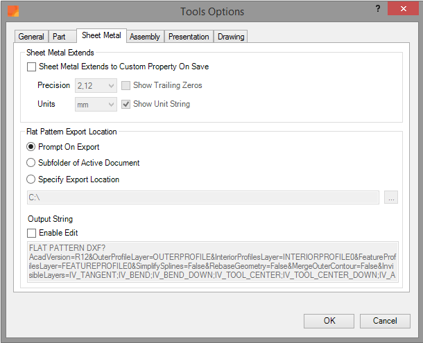
Specifies how the flat patterns will be exported. By enabling the checkmark the 'Output String' can be manually changed. It is recommended to first copy the existing string, using CTRL-C, to a text file. In which you can modify the string. After performing the changes, you can copy the new string back into the 'Output String' text field.
The ‘Output String’ consists of a number of arguments stitched together using '&' (ampercents). The table below shows the possible options.
Argument |
Type |
Default Value |
Note |
TangentLayer |
String |
IV_TANGENT |
|
OuterProfileLayer |
String |
IV_OUTER_PROFILE |
|
ArcCentersLayer |
String |
IV_ARC_CENTERS |
|
InteriorProfilesLayer |
String |
IV_INTERIOR_PROFILES |
|
BendUpLayer |
String |
IV_BEND |
|
BendDownLayer |
String |
IV_BEND_DOWN |
|
ToolCenterUpLayer |
String |
IV_TOOL_CENTER |
|
ToolCenterDownLayer |
String |
IV_TOOL_CENTER_DOWN |
|
FeatureProfilesUpLayer |
String |
IV_FEATURE_PROFILES |
|
FeatureProfilesDownLayer |
String |
IV_FEATURE_PROFILES_DOWN |
|
AltRepFrontLayer |
String |
IV_ALTREP_FRONT |
|
AltRepBackLayer |
String |
IV_ALTREP_BACK |
|
UnconsumedSketchesLayer |
String |
IV_UNCONSUMED_SKETCHES |
|
TangentRollLinesLayer |
String |
IV_ROLL_TANGENT |
|
RollLinesLayer |
String |
IV_ROLL |
|
***Color |
String |
|
*** indicates name of layer from the argument column. RGB values separated by ;. Example: TangentLayerColor=255;0;0 |
***LineType |
Long |
|
*** indicates name of layer from the argument column. Long value from LineTypeEnum. Example: TangentLayerLineType=37644 |
***LineWeight |
Double |
|
*** indicates name of layer from the argument column. Value in centimeters. Example: TangentLayerLineWeight=.1016 |
ExportUnconsumedSketchProperties |
Boolean |
True |
Specifies whether individual sketch entity properties should be exported. If set to False, the properties specified by the UnconsumedSketchesLayer are used. |
AcadVersion |
String |
|
2010, 2007, 2004, 2000, or R12 (for DXF only) |
SimplifySplines |
Boolean |
True |
Enable spline replacement by linear segments |
SplineTolerance |
Double |
0.01 |
Chord tolerance for spline replacement |
AdvancedLegacyExport |
Boolean |
True |
|
MergeProfilesIntoPolyline |
Boolean |
False |
Build a polyline of the exterior profiles |
RebaseGeometry |
Boolean |
False |
Move geometry to 1st quadrant |
InvisibleLayers |
String |
|
List of layer names to make invisible, separated by ; |
Values for ***LineType: |
||
|
37644 |
kChainLineType |
|
37633 |
kContinuousLineType |
|
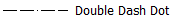
37638 |
kDashDottedLineType |
|
37645 |
kDashedDoubleDottedLineType |
|
37641 |
kDashedHiddenLineType |
|
37634 |
kDashedLineType |
|
37647 |
kDashedTripleDottedLineType |
|
37636 |
kDottedLineType |
|
37639 |
kDoubleDashDoubleDottedLineType |
|
37637 |
kDoubleDashedChainLineType |
|
37646 |
kDoubleDashedDottedLineType |
|
37640 |
kDoubleDashedTripleDottedLineType |
|
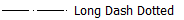
37642 |
kLongDashDottedLineType |
|
37635 |
kLongDashedDoubleDottedLineType |
|
37643 |
kLongDashTripleDottedLineType |
Many arguments may be specified in the 'Output String', as can be seen in the table above. For some arguments also the default value is shown. Whenever the argument is not explicitly specified, the default value will be used.
Multiple arguments can be specified by stitching the arguments together using an ‘&’
Examples:
To generate a DXF file in AutoCAD format version 12, using a layer name 'Outer' in which the curves of the outer-contour will be placed:
FLAT PATTERN DXF?AcadVersion=R12&OuterProfileLayer=Outer
To generate a DXF file in AutoCAD format version 12, using a layer name 'Outer' in which the curves of the outer-contour will be placed. Setting the layer color to Red (RBG 255;0;0):
FLAT PATTERN DXF?AcadVersion=R12&OuterProfileLayer=Outer&OuterProfileLayer Color=255;0;0
To generate a DXF file in AutoCAD format version 12, using a layer name 'Outer' in which the curves of the outer-contour will be placed. Setting the layer color to Red (RBG 255;0;0) and the line type to Chain(37644):
FLAT PATTERN DXF?AcadVersion=R12&OuterProfileLayer=Outer&OuterProfileLayer Color=255;0;0&OuterProfileLayerLineType=37644